Customized Open Self-Rolling Textile Sleeve for Automation Systems

In today's automated assembly systems, proper cable protection is key to smooth and reliable operation. Continuous movement, vibration, and high temperatures can easily damage insulation, cause short circuits, and even lead to unexpected downtime and costly repairs.


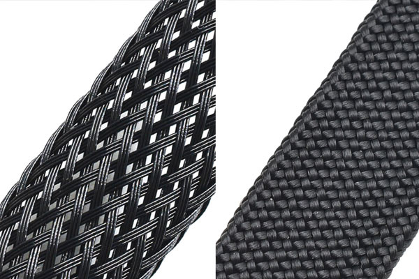
open self-rolling textile sleeve


Some customers in the automation equipment manufacturing industry have turned to us for a durable and easy-to-install open self-rolling textile sleeve to protect and organize their cables and wire harnesses.

Customer Requirements
Some automation projects require open self-rolling textile sleeves in the following sizes: 10, 16, 20, 25, 38, and 50mm. If your needs focus on quick installation over pre-assembled cables or abrasion and heat resistance in moving parts, then a flexible textile sleeve that adapts to different diameters is ideal.


MJ Solution: Open Self-Rolling Textile Sleeve Series

Based on these challenges, MJ recommended our open self-rolling textile sleeve, a versatile and efficient cable protection sleeve designed for industrial use.

1. Self-Closing Split Design
The open and self-wrapping structure allows the sleeve to be quickly wrapped around cables — ideal for maintenance and retrofitting. Compared with traditional braided tubes, the open self-rolling textile sleeve can reduce wiring time by up to 70%.

2. Durable PET Construction
Made of high-strength polyester monofilament, it offers:
  • Temperature range: –50°C to +150°C
  • Excellent abrasion resistance and flame retardancy (UL94 V0 optional)
  • Stable performance in automotive, automation, and electronic environments

3. Multiple Sizes and Expandability

From 10mm to 50mm, the open self-rolling textile sleeve adapts easily to different cable bundles, reducing stock complexity while covering a broad range of applications.

4. Aesthetic and Functional Management

Besides protection, this textile braided sleeve enhances cable organization and keeps the automation line clean, improving both safety and visual quality.

Application Areas
Area Typical Diameter Function
Control cabinets 10–16mm Organizing signal cables
Robot arms / conveyor systems 20–25mm Anti-abrasion cable protection
Power / pneumatic lines 38–50mm Heavy-duty cable shielding

The Open Self-Rolling Textile Sleeve is ideal for:
  • Cable drag chains
  • Robot harness systems
  • Motor and sensor wiring
  • Automation control units

This solution provides automation systems with a long-term cable management system that ensures both reliability and flexibility under industrial conditions.

How PEEK Braided Sleeving Resists Chemical Corrosion in Harsh Environments

When it comes to protecting sensitive cables, fiber optics, and wire harnesses exposed to chemicals, lubricants, and cleaning fluids, PEEK braided sleeving stands out as one of the most advanced protection solutions available today. But how exactly does it resist corrosion — especially when it's not a sealed tube?


PEEK Braided Cable Sleeve


1. The Secret Lies in Its Molecular Structure

PEEK (Polyether Ether Ketone) is an aromatic, semi-crystalline polymer known for its extraordinary chemical and thermal stability.
Its molecular backbone is made up of:
  • Benzene rings for rigidity and heat resistance,
  • Ketone (–CO–) and ether (–O–) linkages for oxidative and chemical stability.
This unique structure makes PEEK:

  • Virtually inert to most acids, bases, and organic solvents,
  • Non-reactive even at high temperatures (up to 250°C),
  • Unaffected by oils, alcohols, or sterilization agents used in industrial and medical environments.

As a result, the material itself will not degrade, swell, or crack even under long-term chemical exposure.

2. Braided Protection: Deflect, Don't Absorb

Unlike sealed tubing, PEEK braided sleeving is an open mesh structure.
This design doesn’t aim to block liquids completely but instead to minimize chemical impact through:

  • Non-absorbent material: PEEK fibers do not soak up liquids, allowing chemical agents to evaporate or drain quickly.
  • Physical barrier: The sleeving keeps aggressive fluids away from the cable jacket, reducing direct surface contact.
  • Fast drying: Its woven structure prevents moisture buildup, avoiding long-term exposure or chemical pooling.

In other words, while it doesn’t create a watertight seal, it offers a chemically inert and self-cleaning protective layer.

3. Compared to Other Materials


Property PET/Nylon Sleeving PEEK Braided Sleeving PEEK Heat Shrink Tubing
Chemical resistance Poor – absorbs and softens Excellent – chemically inert Excellent – fully sealed
Temperature range up to 125°C up to 250°C up to 260°C
Flexibility High High Medium
Application General cable management Harsh environments, optical fibers Sealed protection

Thus, PEEK braided sleeving delivers the best combination of flexibility, high-temperature endurance, and chemical stability — outperforming traditional PET or nylon sleeves in nearly all harsh conditions.

4. Real-World Applications

PEEK braided sleeving is commonly used in:

  • Laser and medical fiber optic systems — protects delicate fibers from sterilization agents and lubricants.
  • High-temperature wire harnesses — resists oils, hydraulic fluids, and solvents in automotive or aerospace systems.
  • Industrial sensors and actuators — ensures long-term insulation and protection against corrosive chemicals.

In laser or medical fiber applications, PEEK sleeving is often paired with an outer PTFE or silicone jacket, forming a dual-layer protection system that virtually eliminates chemical degradation.

PEEK braided sleeving does not rely on complete sealing — it relies on material intelligence.
By combining chemical inertness, thermal endurance, and mechanical strength, it provides a superior solution for protecting critical cables and fibers operating in aggressive environments.

Whether used in laser optics, medical devices, or industrial cable systems, PEEK braided sleeving ensures lasting protection where conventional materials fail.

Reliable EMI Shielding Sleeves for Hydrogen Energy and Power Electronics Systems

In hydrogen electrolysis systems, power electronics, and precision control devices, electromagnetic compatibility (EMC) has always been a core challenge in engineering design.


As system power density increases and signal transmission becomes more complex, issues such as electromagnetic interference (EMI) and radio frequency interference (RFI) become more prominent. These disturbances can cause signal distortion, sensor malfunction, and even equipment failure.


To address these problems, engineers are increasingly adopting flexible braided shielding sleeves with grounding straps, which feature excellent conductive shielding and reliable grounding design. This provides sensitive electronic systems with effective protection against interference.

However, several technical challenges remain within such systems.

For instance, hydrogen electrolyzers and power units generate high currents and high-frequency pulse signals during operation. These electromagnetic fields can easily couple into sensors, PLC control lines, or communication lines, leading to signal fluctuations, data anomalies, or control malfunctions.

In complex systems, poor grounding or inconsistent ground potential in the shielding layer can create ground loops, resulting in noise interference or signal drift.
Inside electrolyzers or control cabinets, signal cables and power cables are often routed in parallel.
Without effective shielding isolation, crosstalk and signal coupling may occur, affecting communication stability.
Over time, cables are also subjected to mechanical stress, vibration, and friction, which can cause conventional shielding meshes to loosen, break, or lose their shielding effectiveness.


MJ's Technical Solution

MJ specializes in high-performance wire harness protection and shielding technology.
Through the independently developed Braided Shielding Sleeve with Grounding Strap series, MJ provides systematic protection solutions for hydrogen energy and industrial electronic systems.

1. Electromagnetic Shielding & Signal Integrity
MJ uses high-purity tinned copper wires precisely woven into a 360° conductive shield.
This effectively blocks external electromagnetic fields, reduces signal noise, and ensures stable signal transmission.

2. Integrated Grounding Design
The sleeve features an internal grounding strap that connects directly to the equipment chassis or ground terminal, ensuring consistent shield potential, eliminating ground loop effects, and enhancing EMC performance.

3. Flexible Split Design
The side-entry (split) structure allows installation without disconnecting cables — ideal for confined spaces such as control cabinets, PEM electrolyzers, and instrument boxes.
This design enables quick maintenance and replacement, significantly reducing assembly time.

4. Enhanced Environmental & Mechanical Protection
The tinned copper layer offers excellent corrosion and high-temperature resistance, while the braided construction itself provides superior flexibility and mechanical durability.


System Application of MJ Products

Application Area Function Typical Role
Electrolyzer Harness EMI Shielding & Grounding Protection Ensures stable sensing and monitoring signals
Power Control Cabinets High-Frequency Noise Suppression Protects control circuits from interference
Communication & Data Transmission Cables Signal Integrity Protection Reduces communication errors and latency
Equipment Grounding Systems Ground Equalization Eliminates ground loops and potential drift

We uphold the mission of providing safe, reliable, and high-performance cable protection and connectivity solutions.
Our braided shielding products, manufactured through rigorous material selection and process control, are widely used in:

  • Hydrogen energy and energy storage systems
  • Power electronics and automation equipment
  • New energy vehicles and rail transit
  • Communication and industrial control systems
By offering customizable lengths, various shielding densities, and grounding strap configurations, MJ helps engineers worldwide achieve more stable, efficient, and safe electrical systems even in high-interference environments.

The Engineering Value of Braided Sleeving in New Energy Vehicles (NEV)

As the architecture of new energy vehicles (NEVs) evolves toward higher voltage, lightweight construction, and greater system integration, the reliability and safety of wiring harnesses have become a critical engineering focus. Acting as the “neural network” of the vehicle, harness systems require comprehensive protection against mechanical, electrical, and thermal challenges.


Within this context, braided sleeving has evolved from a simple harness organizer into a system-level protective component that directly impacts electrical safety, EMC performance, and long-term durability.


1.Key Application Areas — Where & Why

In NEVs, braided sleeving is deployed across multiple key harness zones, each with specific engineering objectives:

  • High-Voltage Harness (Battery ↔ Inverter / Motor / DC-DC)
Provides mechanical protection, insulation cut-through resistance, and, when required, electromagnetic shielding. Maintains thermal stability and fire resistance to ensure HV system safety.
  • Battery Module and Pack Internal Harnesses
Prevents insulation wear caused by vibration or friction. Expandable or split-sleeve designs allow easy maintenance and module replacement.
  • On-Board and External Charging Cables
Must be abrasion-resistant, UV- and oil-resistant, while maintaining flexibility for user handling and storage.
  • Power Electronics and Motor Bay (Inverter, PDU, DC-DC)
Requires high-temperature-resistant, flame-retardant, and optional shielding sleeving for reliable performance near heat sources.
  • Body Control and Signal Harness (CAN / LIN / Sensor)
Ensures cable organization, EMC separation, and visual identification, supporting efficient vehicle assembly and serviceability.


2. Common Challenges & Engineering Responses

Wiring harnesses in NEVs face unique stresses such as high voltage, EMI interference, thermal aging, vibration, and maintenance complexity. Braided sleeving provides practical engineering countermeasures:

Challenge Engineering Response
High Voltage / EMI Risk Use conductive or tinned copper wire braided shields with proper grounding and terminal treatment.
Thermal Cycling & High-Temperature Aging Select high-temperature materials such as fiberglass, PTFE, or aramid blends; apply thermal insulation where needed.
Vibration & Mechanical Abrasion Employ dense or dual-layer constructions (outer abrasion-resistant layer + inner warning color).
Assembly & Maintenance Efficiency Use side-entry or zipper-style sleeves to reduce disassembly and rework time.
Compliance & Certification Ensure materials meet UL94, IEC 60332, RoHS, and REACH standards.


3. Material & Structural Trade-offs

Choosing the right material and structure helps balance cost, protection, and assembly efficiency:

  • PET (Polyester) Braided Sleeve — Lightweight, abrasion-resistant, cost-effective, recyclable; ideal for low-heat areas.
  • Fiberglass Sleeve — Excellent thermal resistance (up to 250°C short-term) and flame retardancy.
  • Aramid / Kevlar® Reinforced Sleeve — Exceptional cut and tensile strength; ideal for critical high-protection zones.
  • PTFE / Fluoropolymer Sleeve — Superior chemical and thermal resistance, low friction coefficient.
  • Metallic / Tinned Copper Braid — Provides EMI shielding; requires proper grounding to ensure effectiveness.

Structural Options:
  • Full Braided for continuous protection.
  • Split or Side-Entry for easy installation and service.
  • Dual-Layer for extreme abrasion zones.
  • Self-Closing or Zipper Type for quick assembly and rework.


4. Design & Engineering Checklist


To achieve high reliability in NEV applications, the following parameters should be incorporated into the design phase:

  1. Functional Segmentation: Classify each harness by function (HV Power, LV Signal, Communication, Sensor).
  2. Temperature Rating: Define continuous and peak operating temperatures.
  3. Mechanical Protection: Specify abrasion, cut-through, and bending endurance requirements.
  4. EMC Requirements: Determine shielding coverage, grounding method, and connection design.
  5. Assembly Constraints: Evaluate space, process method (manual or automated), and maintenance needs.
  6. Aesthetics & Identification: Apply colors, stripes, or printing for traceability.
  7. Regulatory Compliance: Confirm material certification (UL94, IEC 60332, RoHS, REACH, ISO 26262).
  8. Maintenance Strategy: Consider modular designs for easy section replacement.


5. Validation & Testing Matrix

To ensure real-world reliability, validation testing should be included during prototype and PPAP stages:

  • Thermal cycling and aging (LV124 / ISO 16750)
  • Vibration and mechanical fatigue testing
  • Flexural fatigue and bending endurance
  • Abrasion and cut-through resistance
  • Flammability and smoke density (UL94, IEC 60332)
  • Salt spray and chemical resistance
  • EMC shielding effectiveness
  • Post-aging insulation integrity


6. Typical Engineering Scenarios

Scenario A: 800V High-Voltage Main Loop
Recommended configuration: outer PET or aramid abrasion-resistant layer + inner fiberglass thermal layer + local tinned copper shield braid with grounded terminals.
Validation focus: grounding continuity, short-circuit tolerance, thermal durability.

Scenario B: Battery Module Interconnect Harness
Recommended configuration: split-type fiberglass or aramid sleeve with visible warning color for maintenance visibility and easy replacement.

7. Actionable Guidelines for OEMs / Tier-1 Suppliers

  1. Define a "Sleeving Grade Matrix" based on harness function (HV, LV, Signal, Charging).
  2. Include test items in the supplier specifications (SOQ / PPAP) and require material certificates.
  3. Validate early during prototype phase to catch assembly or EMC issues.
  4. Standardize assembly tools and processes, such as crimping and grounding methods.
  5. Adopt modular maintenance designs for battery and power electronics harness sections.

8. Conclusion: From a "Finishing Part" to a "System Protector"

In NEVs, braided sleeving has evolved far beyond aesthetics or cable organization. It now serves as a critical protection system safeguarding electrical safety, electromagnetic compatibility, thermal stability, and long-term durability.

With advanced material engineering, structural innovation, and strict validation,MJ provides comprehensive braided sleeving solutions that help global OEMs and Tier-1 suppliers achieve higher reliability, easier maintenance, and improved overall system safety.


Why PET Braided Structure Effectively Resists Friction and Contact with Sharp Edges

In demanding industrial, automotive, and electrical applications, cables are constantly exposed to vibration, friction, and contact with sharp edges. Over time, these factors can cause severe wear, insulation damage, and even system failure. To ensure long-term cable reliability and protection, PET braided sleeving has become an essential solution.


Engineered from durable polyethylene terephthalate (PET) monofilaments, this braided mesh structure offers exceptional abrasion resistance, flexibility, and thermal stability. More than just a protective covering, the PET braided sleeve acts as a dynamic shield, dispersing mechanical stress and preventing direct damage to the cable surface — even in harsh environments.

Stress Distribution to Prevent Local Damage
PET braided sleeving is composed of multiple interwoven filaments that form a cross-mesh structure. When sharp or abrasive objects make contact, the impact force is not concentrated on one point but is evenly distributed through the interlaced PET strands, significantly reducing the risk of surface damage to the cable.

Acts as a Protective Buffer Layer
The PET braided mesh serves as the first protective barrier, absorbing and dispersing mechanical energy from external friction or impact before it reaches the cable insulation. This buffer layer minimizes wear and extends the service life of the wiring system.

Flexible and Dynamic Protection
The PET braided structure is highly flexible, allowing it to move naturally with the cable during bending or vibration. Unlike rigid conduits, this flexibility prevents stress concentration and provides long-term abrasion resistance under dynamic conditions.

Reduced Friction through Multi-Point Contact
The mesh surface of the PET braided sleeve consists of numerous contact nodes instead of a flat surface. During operation, only a few points contact at any given time, lowering the overall friction coefficient. The interwoven filaments can also slide slightly against each other, offering an internal cushioning effect that further reduces wear.

High-Performance Material Properties
PET monofilaments are known for their excellent abrasion resistance, self-lubricating performance, and thermal stability. Even under contact with sharp metal edges or rough surfaces, the PET braided sleeve resists breakage, maintaining integrity and reliability in harsh environments.

Example in Application

In automotive engine compartments or industrial control systems, cable harnesses often face friction from metal edges or bolts.

Without protection: Cables rub directly against hard surfaces, causing insulation failure or short circuits.

With PET braided sleeving: The outer layer absorbs impact, disperses stress, and protects the cable core, ensuring long-lasting reliability and safety.

How a Polyester PET Sleeving with Dispenser Box Improves Automotive and Industrial Wiring

Efficient and organized cable management is essential in modern industrial and automotive production. Our Polyester PET Sleeving with a dispenser box design allows operators and technicians to quickly pull out the required length, saving installation and preparation time while keeping workspaces tidy and organized.


Applications

Automotive dashboards, door harnesses, and household appliance control panels.

Features & Benefits: On production lines, wiring harnesses often consist of cables with varying diameters and lengths, requiring frequent cutting and sleeving. Traditional bulk rolls can become tangled and difficult to handle. With dispenser-box braided sleeving, operators can quickly pull out the required length without untangling the roll, saving setup time. Multiple technicians can use the box simultaneously, improving workflow efficiency and harness assembly consistency.
Factory control cabinets, automation equipment, and motor cable protection.

Features & Benefits: In industrial wiring, engineers need to route multiple cables of varying lengths. Dispenser-box braided sleeving allows quick extraction and cutting to the required length, avoiding messy bulk rolls. The boxed design is easy to carry and store, keeping workspaces organized and improving wiring efficiency.

On-site maintenance and electrical service personnel, for quick cable replacement or organization.
Features & Benefits: In field service environments, technicians often need to quickly handle cables and replace sleeving. The dispenser box design makes the sleeving portable, organized, and easy to cut, enabling fast installation or replacement even in confined or complex spaces, improving efficiency and safety.


Our dispenser-box Polyester PET Sleeving enhances workflow efficiency while ensuring cable protection and organized management, making it an ideal solution for automotive, industrial, and electronic applications.


EV Wiring Harness Requirements for Autonomous & ADAS Systems


As electric vehicles (EVs) rapidly evolve, the wiring harness has become a critical backbone of the vehicle’s electrical and electronic architecture. With the growing integration of autonomous driving technologies and Advanced Driver Assistance Systems (ADAS), the requirements for EV wiring harnesses are becoming more stringent. Ensuring safety, reliability, and efficiency is no longer optional—it is a necessity for manufacturers and suppliers aiming to compete in the global market.

Why Wiring Harnesses Are Critical in EVs

The wiring harness functions as the “nervous system” of the electric vehicle. It carries power and signals to every component, from the battery pack to sensors, cameras, radars, and control units. In autonomous and ADAS-equipped vehicles, the wiring harness must support:

  • High-speed data transmission for cameras, LiDAR, radar, and ultrasonic sensors.

  • High-voltage power delivery to batteries, inverters, and motor controllers.

  • Signal integrity to ensure safety-critical functions like emergency braking or lane-keeping.

Without a robust wiring harness system, even the most advanced ADAS technologies cannot operate reliably.


Key Requirements for EV Wiring Harnesses in Autonomous & ADAS Systems

1. High Data Bandwidth

Autonomous and ADAS functions rely on multiple sensors generating large amounts of data. The harness must integrate high-speed Ethernet cables, coaxial cables, and fiber optics to ensure real-time communication between electronic control units (ECUs).

2. EMI & EMC Protection

Electromagnetic interference (EMI) can disrupt signal accuracy. Shielded cables and optimized harness layouts are essential to maintain electromagnetic compatibility (EMC), especially in vehicles with multiple high-frequency devices.

3. Lightweight & Compact Design

With EVs, weight reduction directly impacts driving range. Using aluminum wiring, optimized routing, and modular harness structures can help reduce total vehicle weight while meeting performance standards.

4. Thermal & Mechanical Durability

Wiring harnesses must withstand harsh conditions, including high temperatures, vibration, bending, and chemical exposure. Advanced insulation materials such as cross-linked polyethylene (XLPE) or fluoropolymers provide the necessary durability.

5. Safety Standards & Redundancy

Since ADAS systems control safety-critical functions, harnesses must be designed with redundant pathways, fire resistance, and compliance with ISO 26262 (functional safety) standards.

6. Integration with High-Voltage Systems

Autonomous EVs often operate with 400V to 800V systems. Harnesses must handle high-voltage insulation requirements while minimizing power loss and ensuring operator safety.


Challenges in Developing EV Wiring Harnesses

  • Complexity: The number of sensors, cameras, and modules increases wiring complexity.

  • Space Constraints: Harnesses must fit into compact EV architectures without compromising airflow or cooling.

  • Cost Pressure: Manufacturers must balance high-performance requirements with cost-efficient materials and production.


Future Trends in EV Wiring Harness Development

  1. Zonal Architecture – Instead of one large harness, vehicles are shifting to zonal systems that reduce wiring length and weight.

  2. High-Voltage Standardization – Standardized HV connectors and harnesses for EV platforms will streamline manufacturing.

  3. Smart Harnesses – Incorporating diagnostic functions for real-time monitoring of harness performance.

  4. Advanced Materials – Wider use of lightweight conductive materials like aluminum and composites.


As autonomous driving and ADAS adoption accelerate, EV wiring harnesses will continue to evolve from simple power delivery systems to high-performance communication and safety enablers. Manufacturers and suppliers must prioritize data transmission, safety compliance, weight reduction, and thermal durability to meet the rising demands of next-generation EVs.

Investing in advanced wiring harness solutions is no longer just an engineering choice—it is a strategic move to ensure competitiveness in the fast-growing EV and autonomous vehicle markets.


How NTC Wire Harnesses Improve Efficiency in New Energy Vehicles


The rise of new energy vehicles (EVs and hybrid cars) has put the spotlight on electrical system efficiency. A key component that often goes unnoticed is the NTC wire harness, which plays a critical role in improving performance, reducing energy loss, and ensuring safety. For manufacturers and fleet operators seeking high performance EV wiring solutions, investing in quality NTC wire harnesses is a smart choice.


1. What is an NTC Wire Harness?

An
NTC (Negative Temperature Coefficient) wire harness is designed to manage heat and electrical resistance in circuits efficiently. Unlike traditional wiring, NTC wire harnesses provide:


What Safety Rules Should Be Followed When Wiring Solar Panels with High-Current Connectors?


Wiring solar panels is one of the most critical steps in building a reliable solar power system. When high-current connectors are involved, the risks and technical requirements become even more significant. A poorly executed connection can lead to overheating, power loss, fire hazards, or long-term system degradation. On the other hand, proper wiring ensures stable performance, improved efficiency, and safety for both residential and commercial installations.

To help installers, technicians, and system owners, here are the key safety rules that should always be followed when wiring solar panels with high-current connectors.


1. Choose the Right Connectors for Solar Applications

Not all connectors are suitable for photovoltaic systems. Solar power generates DC electricity, which behaves differently from AC systems and requires connectors that can handle continuous current flow. PV solar connectors for wiring are designed specifically for this purpose. They feature locking mechanisms to prevent accidental disconnection, weather-resistant housings for outdoor durability, and low-resistance contact points to minimize energy loss.

Using general electrical plugs or mismatched connectors can increase the risk of arcing, which not only reduces system efficiency but also poses a fire hazard. Installers should ensure that every connector is compatible with the panel’s specifications and rated for the system’s maximum voltage and current.


2. Select the Proper Cable Size and Insulation

The performance and safety of a solar installation are highly dependent on the correct choice of cables. Cable diameter must be matched to the system’s voltage and current to prevent overheating. For example, in high-capacity systems, undersized cables may create excessive resistance, leading to dangerous heat buildup.

Additionally, solar panel wiring safety requires cables to have robust insulation. Outdoor environments expose wires to UV radiation, humidity, and temperature fluctuations, so the insulation should be flame-retardant, weather-resistant, and rated for DC applications. Using cables specifically certified for solar use helps minimize risks of short circuits or electrical faults.


3. Double-Check Polarity and Secure All Connections

Reversing polarity when connecting panels is a common error, especially in larger arrays with multiple strings of panels. A single reversed connection can cause damage to charge controllers, inverters, or batteries. To prevent this, polarity should always be checked with a multimeter before making final connections.

Connection security is equally important. Loose joints or poor crimping can create high resistance points, resulting in arcing or intermittent failures. This is where high current solar connectors make a significant difference—they are engineered to provide reliable electrical contact under high load conditions while locking firmly into place to withstand vibration, temperature changes, and outdoor exposure.


4. Implement Proper Grounding and Protection Devices

Grounding the solar power system is essential for both safety and compliance with electrical standards. A properly grounded system helps prevent electric shock and minimizes damage from lightning strikes or electrical surges.

In addition to grounding, installers should integrate protective devices such as fuses, circuit breakers, and surge protectors. These devices ensure that if a fault occurs, it can be isolated quickly to prevent further damage to equipment or danger to personnel.


5. Perform Regular Inspections and Preventive Maintenance

Even the best installations require ongoing attention. Over time, connectors may loosen, seals can degrade, or dust and moisture may affect electrical contact. Regular inspections allow these issues to be detected early.

Preventive maintenance should include:

  • Checking connectors for discoloration or overheating marks.

  • Ensuring all locking clips and seals remain intact.

  • Cleaning connectors to remove dust or debris.

  • Verifying cable insulation is free from cracks or cuts.

Proactive care extends system life, improves reliability, and keeps energy production consistent.


Wiring solar panels with high-current connectors requires more than just technical skill—it demands strict adherence to safety rules. From choosing the right solar-specific connectors to ensuring correct polarity, grounding, and ongoing maintenance, every step plays a role in preventing hazards and optimizing performance.

By applying these principles, solar installations can deliver reliable energy while maintaining the highest levels of safety and efficiency.

What's the Difference Between a Connector and a Terminal?

In electrical engineering and wiring systems, people often confuse the terms connector and terminal. At first glance, they may seem interchangeable, but in practice, they serve different purposes. Understanding their distinctions is essential for ensuring safe, efficient, and long-lasting electrical installations.

Non-Insulated Cord End Terminal Apply In Flexible WireNylon-Insulated Cord End Terminal Apply In Flexible Wire

Connector vs. Terminal: Core Definitions

  • Connector: A device that joins two or more electrical circuits together. It usually includes housings, locking mechanisms, and sometimes multiple terminals inside. Connectors can be disconnected and reconnected without tools in most cases.

  • Terminal: The specific end-point or interface where a wire is physically attached. A terminal may involve crimping, soldering, or fastening to secure the wire and ensure current transfer. Unlike connectors, terminals focus more on the actual wire-to-contact interface.


In short, every connector may contain several terminals, but not every terminal is part of a connector assembly.


Why Terminals Matter in Electrical Systems

Terminals are critical because they directly affect conductivity, resistance, and heat generation. A poor-quality terminal increases resistance, leading to voltage drops and possible overheating. In industrial machinery, even a 0.05 Ω increase in resistance at a terminal can raise localized heat by 15–20°C, significantly reducing wire lifespan.


For applications such as automotive wiring, industrial control cabinets, and power distribution, selecting the right terminal type is as important as choosing the wire itself.


Common Types of Terminals

Different environments and electrical loads require specific terminal types. Below are some widely used ones:

Terminal Type Material/Design Typical Use Case Advantages
Nylon-Insulated Cord End Terminal Copper with nylon sleeve Control panels, fine-stranded wires Prevents wire strand fraying, easy crimp
Copper Tube Terminal Pure copper tube, tinned High-current connections, battery cables Low resistance, excellent conductivity
Non-Insulated Cord End Terminal Bare copper ferrule Compact spaces, where insulation is not required Economical, reliable crimping option


Nylon-Insulated Cord End Terminal

This type of terminal is widely used in control cabinets and distribution boxes. The nylon insulation prevents wire strands from spreading, ensuring that every copper strand carries current evenly. According to IEC standards, ferrules can improve wire stability by up to 40% during repeated insertions into terminal blocks.


For example, in a 2.5 mm² fine-stranded wire, without a ferrule, insertion losses may increase by 12–15%. With a Nylon-Insulated Cord End Terminal, the strands remain aligned, improving current efficiency and reducing long-term loosening.


Copper Tube Terminal

When dealing with higher currents, such as battery connections, motor leads, or inverter outputs, the Copper Tube Terminal is the most reliable choice. Copper’s conductivity is about 58 MS/m, nearly 10 times higher than aluminum, which means less heat build-up and lower power loss.


These terminals are often tinned to resist oxidation and can handle currents above 100 A depending on cable size. In automotive applications, a copper tube terminal can reduce joint heating by nearly 25% compared to generic crimp lugs.


Non-Insulated Cord End Terminal

Not every application requires insulation. In compact spaces or when the terminal is later inserted into an insulated housing, the Non-Insulated Cord End Terminal becomes the economical and practical option.


Despite being simple, it ensures that multi-strand wires do not deform under screw pressure. Field data shows that properly crimped non-insulated ferrules can reduce wiring faults by over 30% in industrial control panels compared to wires left bare.


Choosing Between Connector and Terminal

When should you focus on terminals rather than connectors?

    1.Terminals are best when:

    • The priority is conductivity and secure wire contact.

    • The wire will be fixed inside a block, panel, or lug.

    • The installation requires minimal contact resistance.


    2.Connectors are best when:

    • You need quick disconnection and reconnection.

    • Multiple circuits must be joined in a modular housing.

    • Environmental protection (waterproofing, vibration resistance) is essential.


For instance, a solar inverter may use connectors on the panel side for easy maintenance, but inside the inverter box, the wires are fixed with terminals for maximum stability.


The Bigger Picture

Although the words connector and terminal are often used interchangeably, they serve different functions in electrical systems. Connectors focus on modularity and convenience, while terminals concentrate on conductivity and long-term reliability.


As electrical systems grow more complex—whether in electric vehicles, renewable energy, or industrial automation—the performance of terminals like the Nylon-Insulated Cord End Terminal, Copper Tube Terminal, and Non-Insulated Cord End Terminal will directly impact efficiency and safety. Selecting the correct type for the job is not just a matter of cost but a matter of performance and durability.

© 2025 John Doe All rights reserved.

Powered by Hexo